
PRODUCTS
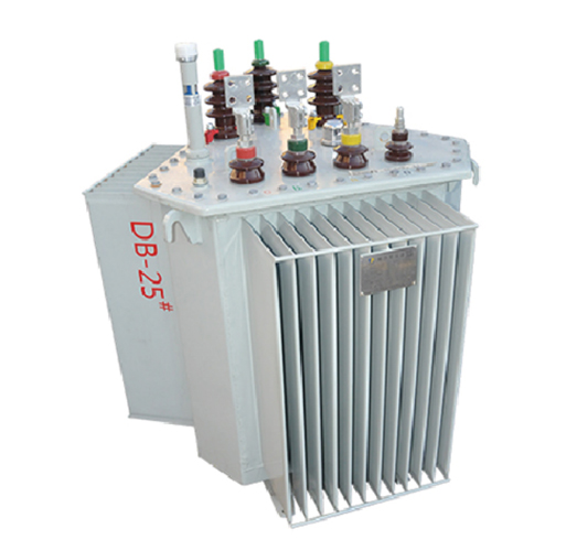
S13 Three-Dimensional Wound Core Oil-immersed Transformer
Low losses: Due to its features—including low joint reluctance, magnetic circuit paths at corners aligned with the magnetic permeability direction of silicon steel sheets, tight winding with high filling factor, and lightweight core—the three-dimensional wound iron-core oil-immersed transformer achieves a 18–28% reduction in no-load loss (Po) and a 50–60% decrease in no-load current (Lo) compared to traditional iron-core oil-immersed transformers.
It offers significant energy-saving benefits and is economically efficient to operate.
Low noise: The noise level of a three-dimensional wound-core oil-immersed transformer is 5–10 dB lower than that of a laminated-core oil-immersed transformer, making it an ideal quiet product.
High mechanical strength: All three-dimensional wound cores feature a perfectly circular cross-section, offering superior short-circuit resistance compared to those with elongated circular sections. Additionally, the high coverage of shims and excellent fastening performance significantly enhance the products short-circuit resistance.
Product Overview
The S11、S13、S20、S22-M series fully sealed oil-immersed power transformer developed and produced by our company has the advantages of low loss, low noise and high efficiency, which can achieve good energy-saving effect and reduce pollution. Fully sealed transformer and ordinary oil-immersed transformer, compared with the elimination of the oil storage cabinet, oil volume changes by the corrugated oil tank corrugated sheet of the elasticity of the automatic adjustment to compensate for the transformer isolated from the air to prevent and slow down the deterioration of the oil and the aging of the insulation, enhance the reliability of the operation, the normal operation of maintenance-free.
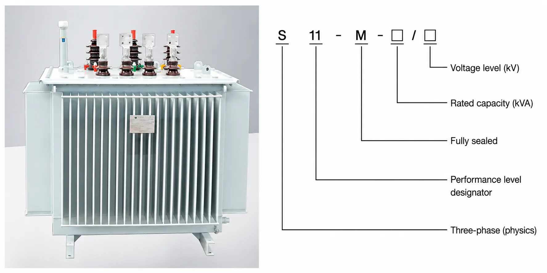
Product Features
◆ Transformer core is made of high quality cold rolled silicon steel sheet stacked together, greatly reducing no-load loss and no-load current, and the core is tied to ensure that the core of the tightness and reduce noise;
◆ High-voltage and low-voltage windings are wound with oxygen-free copper, and the low-voltage winding is of layer-cylinder structure for 315KVA and below. 400KVA and above low-voltage is of foil-winding structure, and the high-voltage winding is of multi-layer-cylinder structure;
◆ Transformer connecting group adopts Dyn11 to reduce the impact of harmonics on the power grid and improve the quality of power supply;
◆ Transformer is fully sealed structure, prolonging service life, free of core lifting, free of maintenance;
◆ The measured noise value is lower than the standard. After normal transportation, this series of transformers can be put into operation without core lifting and checking, installing relevant parts and components, carrying out acceptance project test, and passing the test.
Conditions Of Use
◆ Maximum ambient temperature: +40°C;
◆ Minimum ambient temperature: -25°C;
◆ Altitude: <1000m;
◆ Maximum monthly average relative humidity: 90% (20℃ );
◆ Installation location: installed in places without fire, explosion danger, serious filth, chemical corrosion and severe vibration, indoor or outdoor.
Implementation Standards
GB 1094 Power Transformer
GB/T 15164 Load Guide for Oil-immersed Power Transformers
GB/T 6451 Technical parameters and requirements for three-phase oil-immersed power transformers
GB 2536 Transformer oil
GB 311.1 Insulation fit for HV power transmission and transformation equipment
JB/T 501 Power transformer experiment guidebook
GB 10237 Power transformer insulation level and insulation test air gap of external insulation
DL/T 572 Transformer operation regulations
GB 20052 Power Transformer Energy Efficiency Limit Values and Efficiency Classes
Insulation Level
| voltage level(KV) | Maximum operating voltage (KV) (RMS) | Rated short-time frequency withstand voltage (KV)(RMS)/1min | Rated lightning impulse withstand voltage (KV) (peak) | |
| total wave | intercept (a wave) | |||
| 0.4 | 0.46 | 5 | 75 | 85 |
| 10 | 12 | 35 | ||
| 20 | 23 | 55 | 125 | 140 |
| 35 | 40.5 | 85 | 220 | 200 |
| Model | Rated Capacity(KVA) | Connection Group Number | Voltage Combination(KV) | No-load Loss(W) | Load Losses(W) | No-load Current(%) | Short-circuit Resistance(%) | |||
| High Pressure | Votage Combination | Low Pressure | Dy | Yy | ||||||
| S13-M.RL-30 | 30 | Yyn0 orDyn11 | 106.36 | ±5%±2*2.5% | 0.4 | 80 | 630 | 600 | 0.30 | 4.0 |
| S13-M.RL-50 | 50 | 100 | 910 | 870 | 0.24 | |||||
| S13-M.RL-80 | 80 | 130 | 1310 | 1250 | 0.23 | |||||
| S13-M.RL-100 | 100 | 150 | 1580 | 1500 | 0.22 | |||||
| S13-M.RL-125 | 125 | 170 | 1890 | 1800 | 0.21 | |||||
| S13-M.RL-160 | 160 | 200 | 2310 | 2200 | 0.20 | |||||
| S13-M.RL-200 | 200 | 240 | 2730 | 2600 | 0.19 | |||||
| S13-M.RL-250 | 250 | 390 | 3200 | 3050 | 0.18 | |||||
| S13-M.RL-315 | 315 | 340 | 3830 | 3650 | 0.17 | |||||
| S13-M.RL-400 | 400 | 410 | 4520 | 4300 | 0.16 | |||||
| S13-M.RL-500 | 500 | 480 | 5410 | 5150 | 0.16 | |||||
| S13-M.RL-630 | 630 | 570 | 6200 | 6200 | 0.16 | 4.5 | ||||
| S13-M.RL-800 | 800 | 700 | 7500 | 7500 | 0.15 | |||||
| S13-M.RL-1000 | 1000 | 830 | 10300 | 10300 | 0.14 | |||||
| S13-M.RL-1250 | 1250 | 970 | 12000 | 12000 | 0.13 | |||||
| S13-M.RL-1600 | 1600 | 1170 | 14500 | 14500 | 0.12 | |||||